روتر سیسکو NCS 1000
رشد سریع ظرفیت در دیتاسنترها نیاز به راه حل های نوین در شبکه و در مقیاس ابری(Cloud scale) را ایجاد کرده است که امکان نظارت سریع ، ساده و پیشرفته را فراهم سازد. روتر Network Convergence System 1000 و یا باختصار NCS 1000 سیسکو اولین روتر صنعت شبکه میباشد که میتواند با اندازه 1RU انتقال اطلاعات با ظرفیت 1 تا 2 ترابایت در ثانیه را پشتیبانی کند. این روتر با بهره گیری از Cisco IOS XR قابلیت هایی از جمله 250G DWDM line rate و CFP2 را فراهم میگرداند.
مدل ها و ویژگی ها لایسنس روتر سیسکو NCS 1000
روتر سیسکو NCS 1001 : این روتر با ابعاد 1RU از 3 مازول قابل اتصال پشتیبانی میکند و دارای دو Linux container (LxC) با دو سیستم عامل 64 بیتی IOS XR مجزا با کارایی Control Plane و Admin Plane میباشد.
روتر سیسکو NCS 1002 : برای دستیابی به راندمان بهتر در دیتاسنترها به ظرفیت بیشتری برای پاسخگویی به تقاضای پهنای باند، همراه با یک ابعاد کوچک و استفاده بهینه از انرژی، نیاز می باشد. این روتر با در اختیار گذاشتن همه این موارد و با بهره گیری از نرم افزار از Cisco nLight Silicon برای ترکیب قابلیت Multimodalities با soft-decision Forward Error Correction (SD FEC) استفاده می کند تا نرخ انعطاف پذیری را در مقابل میزان حداکثر عملکرد نوری معامله کند و حداکثر 2Tbps را در ابعاد 2RU فراهم کند دارای دو Linux container (LxC) با دو سیستم عامل 64 بیتی IOS XR مجزا با کارایی Control Plane و Admin Plane میباشد.
روتر سیسکو NCS 1004 : این روتر بصورت مکانیکی به نحوی طراحی شده است تا با کمترین اشغال فضا و انرژی، بیشترین ظرفیت لازمه را ارائه دهد. این روتر با ابعاد 2RU دارای دو منبع تغذیه AC/DC و 3 فن با قابلیت جایگزینی و Redundancy میباشد. همچنین از یک درایو SSD قابل جایگزینی و یک درایو SSD ثابت جهت ذخیره Backup و سیستم عامل های XR پشتیبانی میکند. همچنین شاسی این سوئیچ برای پشتیبانی از چهار Line-Card طراحی شده است و دارای دو Linux container (LxC) با دو سیستم عامل 64 بیتی IOS XR مجزا با کارایی Control Plane و Admin Plane میباشد.
Rapid capacity growth in the data center and between data centers has driven the need for cloud-scale networking solutions that allow for quick and simple turn-up with enhanced monitoring, deliver performance optimization for capacity scale through modulation and baud-rate innovations, and effectively support multiple vendors’ transponder solutions. The Cisco® Network Convergence System 1001 (NCS 1001) delivers all this and more. The Cisco NCS 1001 is a dense wavelength-division multiplexing (DWDM) line system that is mechanically optimized for data center environments; is performance optimized for maximum capacity; and provides complete automation of installation and configuration with real-time and fine-grained monitoring.
Product Features and Benefits
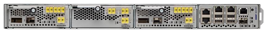
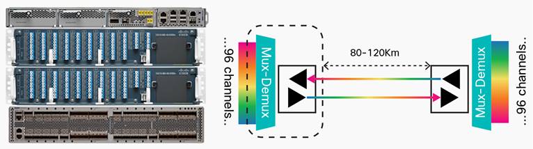
The Cisco NCS 1001 (Figure 1) is a 1RU system that is capable of supporting up to three pluggable modules. The modules can be amplifiers or protection switch modules. The system reuses controller cards and power supplied from the NCS 1002. A 96-channel unprotected point-to-point or a protected point-to-DWDM line system can be implemented with one NCS 1001.
The system operates on a Linux kernel with the carrier-class 64-bit Cisco IOS® XR Software in a Linux container (LxC) and XR system admin plane in a separate LxC. It encompasses a wide variety of features as well as a range of machine-to-machine APIs based on YANG models for ease of configuration and a telemetry agent for a pub-sub model of device monitoring and also provides an infrastructure for third-party applications.
The Cisco NCS 1001 system provides the following hardware benefits (also see Figure 2):
● Up to 23dBm output power to allow for +3dBm per channel fiber launch power and maximum optical performance for high–baud rate and higher order modulation format transponders
● Switchable gain preamplifier up to 34db
● Embedded optical channel monitoring (OCM) module to monitor per channel power at all the input and output ports
● Integrated pluggable optics–based OSC and OTDR support
● OSC support for user data channel transport as well as remote node management
● Unmatched scale and density: line system for 96 channels of C-band in 1RU
● Flex-grid support on OCM module

Amplifier Module
The amplifier module provides the following ports:
● OSC SFP slot
● OTDR XFP slot
● LINE-TX and RX ports
● COM-TX and RX ports
● COM-TX check port
Figure 3 is a functional block diagram of the amplifier module.
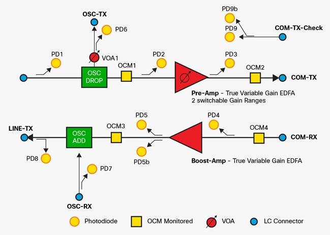
The NCS 1K-EDFA module provides the following functionality:
● Preamplifier (LINE-RX to COM-TX)
◦ Single preamplifier variant, with switchable gain ranges, according to link loss:
◦ Range 1: 0 to 24dB gain, with tilt control; 24 to 27dB gain, with tilt uncontrolled
◦ Range 2: 20 to 34dB gain, with tilt control; 34 to 37dB gain, with tilt uncontrolled
◦ Total 23dBm output power at COM-TX port
● Booster (COM-RX to LINE-TX)
◦ A true variable gain booster amplifier
◦ Gain range: 1 to 20; 20 to 25 uncontrolled tilt.
◦ Total 23dBm output power at LINE-TX port
● Add/drop OSC channel support both 1510nm and 1610nm +/–10nm
● OCM assesses channel presence and gain regulation and per channel power monitoring
Various Amplifier Modes Supported
Users can configure the amplifiers in the following manner.
The amplifier module can be set to manual or autoconfiguration mode. The default mode is manual. The amplifier gain range can also be configured as 25dB (default) or 34dB.
In manual mode, the user sets gain and tilt on the amplifier. The OCM data is not reported on the CLI, but the raw data can be exported. If the user selects auto mode, the user needs to configure the grid (50Ghz/100Ghz/flex) and the per channel power (default +1dBm). OCM data will be reported on the CLI as per grid definition.
Auto mode allows a user with a basic understanding of the optical performance of the link to set up the DWDM system with minimum clicks/effort.
Protection Switch Module
The NCS1K-PSM module (Figure 4) provides the following ports:
● COM-TX and RX ports
● W-TX and RX ports
● P-TX and RX ports

Figure 5 is a functional block diagram of a protection switch module.
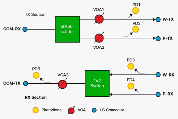
The PSM module provides the following features:
● In TX section:
◦ Splits input optical channels to both working and protection lines.
◦ Forces the switch in the remote site by opening one of the two line paths (by putting the related VOA in AVS).
● In RX section:
◦ Selects the signals from working or protection line. Each line is monitored through a Photo Diode.
◦ Balance the two line losses by changing the VOA attenuation value at the same time as the switch change of state.
● The PSM can be operated in bidirectional switching mode or unidirectional switching mode. In unidirectional switching mode, the following behavior is to be expected:
◦ Splitter on the PSM is bypassed.
◦ Selector on receiver decides what signal to use. If switchover is initiated, PSM does not signal to remote end.
Solution
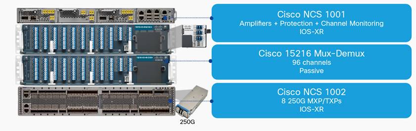
A typical 96-channel 50Ghz spaced point-to-point DWDM system would include 12x NCS 1002 units, 1x MD48-ODDE filter, 1x MD48-EVENE filter, 1x MD48-CME coupler, and 1x NCS 1001. The 24Tbps of capacity would consume only 29RU of rack space. (See Figure 6.)
The two primary configurations supported with the NCS 1001 are the unprotected point-to-point system and the protected point-to-point system. As illustrated in Figure 7, the unprotected configuration requires one amplifier module (NCS1K-EDFA) plugged into the NCS1001-K9 box. OSC add-drop and bidirectional amplification is performed by this module.
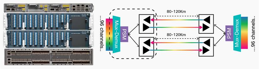
In a protected system, one protection switch module (NCS1K-PSM) and two amplifier modules (NCS1K-EDFA) need to be plugged into an NCS1001-K9 box. The PSM module splits the traffic onto fiber paths, and the far end selects better signal based on optical receive power, thereby providing optical power-based section protection. (See Figure 8.)
Management
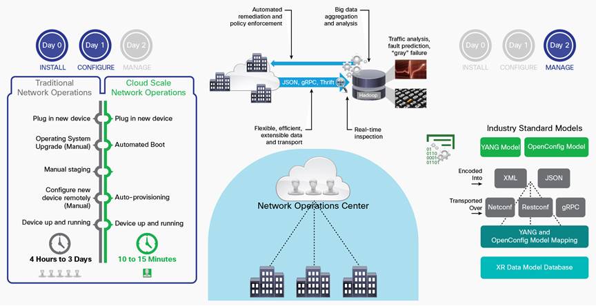
The Cisco NCS 1001 provides comprehensive management capabilities to support operations, administration, maintenance, and provisioning (OAM&P) capabilities through Cisco IOS XR Software CLI, SNMP, Syslog, and XML. In addition, iPXE for automated software download and zero-touch provisioning (ZTP) for automated configuration download are available for simplified installation. For machine-to-machine configuration and management of NCS 1000, different YANG based transport options are available – NETCONF, RESTCONF and gRPC. These can be used over JSON, XML or GPB encoding. The NCS 1000 provides a set of native YANG models as well as the ability to map into any industry-standard or customer-defined YANG models. For monitoring, NCS 1000 provides a streaming telemetry feature that relies on a push mechanism to disseminate user-selected Performance Monitoring and status information at user-specified frequencies at granular 30-second intervals. This improves monitoring speed and scale compared to traditional pull-based mechanisms such as SNMP. Evolved programmable network management (EPN-M) provides a GUI element management system for NCS 1001. (See Figure 9.)
Performance Monitoring
The Cisco NCS 1001 supports both transparent and nontransparent signal transport performance monitoring. Performance monitoring of optical parameters on the client and DWDM line interface includes loss of signal (LOS) and transmit and receive optical power, both aggregate and per channel. Calculation and accumulation of the performance-monitoring data are supported in 15-minute and 24-hour intervals as per G.7710.
Each port incorporates LEDs to provide a quick visual check of the operational status of the card.
Headless Operation
The headless operation allows for the NCS 1001 data plane to operate errorless during software upgrades and when the controller card is either physically absent or in a failed state. All line card statistics will be accumulated and will be available to the user after the controller is up.
Feature Summary
Table 1 summarizes the features of the NCS 1001.
Table 1. Feature Summary
|
Feature |
Description |
|
Software compatibility |
● Cisco IOS XR Software 6.2.1 or later
|
|
Optical feature summary |
● +23dBm output power
● Up to 34dB of preamplifier gain
● Switchable preamplifier gain range
● OCM module for per channel power monitoring at COM and line ports
● Tx and Rx power monitoring
● Line protection
● OSC and OTDR support
|
|
Availability |
● Online insertion and removal of the controller
● Headless mode of operation
|
|
Network management |
● iPXE and ZTP
● Cisco IOS XR Software CLI
● SNMP
● Streaming telemetry
● NETCONF, RESTCONF, gRPC with YANG data-models incl. Open Config.
● EPN-M
|
|
Physical dimensions (NCS1001-K9) |
● Occupies 1RU and fits into 2- or 4-post 19-inch, 21-inch, and 23-inch racks
● Weight: 20 pounds
|
|
Power |
● <200W
|
|
Physical summary |
● Front-to-back straight-through airflow
● 600W DC PSU
● 600W 200/240VAC 10A AC PSU
● 1+1 FRU AC and DC power
● 3+1 FRU fans
● FRU controller
● Removable SSD flash
● 1 console
● 1 RJ45 and 1 GE SFP management port
● 3 USB2.0 3A
● 3 RJ45 UDC (user data channel) ports
● System, trunk, client, fan PSU, locator beacon LEDs
|
|
Environmental conditions |
● Operating temperature: –5 to 55°C
|
Regulatory Compliance
Table 2 lists regulatory compliance information for the trunk card. Note that all compliance documentation might not be completed at the time of product release. Check with your Cisco sales representative for countries other than Canada, the United States, and the European Union.
Table 2. Regulatory Compliance
|
ANSI System |
ETSI System |
|
Countries and Regions Supported |
|
|
● Canada
● United States
● Korea
● Japan
● European Union
|
● European Union
● Africa
● CSI
● Australia
● New Zealand
● China
● Korea
● India
● Saudi Arabia
● South America
|
|
EMC Emissions |
|
|
● ICES-003 Class A
● AS/NZS CISPR 22 Class A
● CISPR 22 Class A
● EN55022 Class A
● FCC 47CFR15 Class A
|
● VCCI Class A
● K32 Class A
● CNS 13438 Class A
● EN61000-3-2 Power Line Harmonics
● EN61000-3-3 Voltage Changes, Fluctuations, and Flicker
|
|
Safety |
|
|
● CSA C22.2 #60950-1 – Edition 7, March 2007
● UL 60950-1 – Edition 2, December 2011
|
● IEC 60950-1 Information technology equipment Safety Part 1: General requirements – Edition 2, 2005 + Amendment 1 2009
● EN 60950-1: Edition 2 (2006) Information technology equipment – Safety – Part 1: General requirements + A11:2009 + A1:2010 + A12:2011
● CE Safety Directive: 2006/95/EC
|
|
EMC Immunity |
|
|
● ICES-003 Class IEC/EN61000-4-2 Electrostatic Discharge Immunity
● IEC/EN61000-4-3 Radiated Immunity
● IEC/EN61000-4-4 EFT-B Immunity
● IEC/EN61000-4-5 Surge
|
● IEC/EN61000-4-6 Immunity to Conducted Disturbances
● IEC/EN61000-4-11 Voltage Dips, Short Interruptions, and Voltage Variations
● K35
|
|
ETSI/EN |
|
|
● EN 300 386 Telecommunications Network Equipment (EMC)
● EN55022 Information Technology Equipment (Emissions
|
● EN55024/CISPR 24 Information Technology Equipment (Immunity)
● EN61000-6-1 Generic Immunity Standard
|
|
Laser |
|
|
● 21CFR1040 (2008/04) (Accession Letter and CDRH Report) Guidance for Industry and FDA Staff (Laser Notice No. 50), June 2007
|
● IEC 60825-1: 2007 Ed. 2.0 Safety of laser products Part 1: Equipment classification, requirements and users guide
● IEC60825-2 Ed.3.2 (2010) Safety of laser products Part 2: Safety of optical fibre communication systems
|
|
Optical |
|
|
● ITU-T G.691
|
● ITU-T G.975
|
|
Quality |
|
|
● TR-NWT-000332, Issue 4, Method 1 calculation for 20-year mean time between failure (MTBF)
|
|
Table 3 provides NCS 1001 specifications, and Table 4 provides ordering information.
Table 3. NCS 1001 Specifications
|
Management |
||
|
Beacon LED |
Blue |
|
|
Client and DWDM port LEDs ● No alarms
● Minor alarms
● Critical and major alarms
|
Green Amber Red |
|
|
Fan LED ● All 4 fans are present and running
● One or more fans are absent or failed
|
Green Red |
|
|
PSU LED ● At least 1 PSU present and operational
● 2 PSUs are present, but one has no power
|
Green Red |
|
|
Status LED ● No active system alarms
● Presence of major or minor alarms
● Presence of critical alarms
|
Green Amber Red |
|
|
Power fully loaded (including pluggable) |
Protection Configuration |
Unprotected Configuration |
|
● Typical
● Maximum
|
250W 300W |
200W 250W |
|
Physical |
||
|
Dimensions |
NCS1001-K9: 17.5” wide x 23.6” deep x 1.73” tall NCS1K-EDFA: 4.2” wide x 9.4” deep x 1.5” tall NCS1K-PSM: 4.2” wide x 9.4” deep x 1.5” tall NCS1K-2KW-DC: 2.9”wide x 10.4” deep x 1.5” tall NCS1K-2KW-AC2: 2.9”wide x 10.4” deep x 1.5” tall NCS1K1-FAN: 1.57” wide x 4.13” deep x 1.57” tall NCS1K-SSD: 3.1” wide x 3.3” deep x 0.5” tall NCS1K-CNTLR2: 6.4” wide x 11” deep x 1.1” tall |
|
|
Weight |
NCS1001-K9: 8.2 Kg (including fans, SSD, and CNTLR) NCS1K-EDFA: 0.84Kg NCS1K-PSM: 0.42Kg NCS1K-2KW-DC: 1.2Kg NCS1K-2KW-AC2: 1.2Kg NCS1K1-FAN: 0.08Kg NCS1K-SSD: 0.4Kg NCS1K-CNTLR2: 1.5Kg |
|
|
Storage temperature |
-28ºC to 70ºC (–20ºF to 158ºF) |
|
|
Operating temperature: normal |
-5ºC to 55°C (23°F to 131°F) |
|
|
Relative humidity ● Normal
● Short-term1
|
5% to 85%, noncondensing 5% to 90% but not to exceed 0.024kg water/kg of dry air |
|
|
1 Short-term refers to a period of not more than 96 consecutive hours and a total of not more than 15 days in 1 year (a total of 360 hours in any given year, but no more than 15 occurrences during that 1-year period). |
||
Table 4. Ordering Information
|
Part Number |
Description |
|
XR-NCS1K-621K9 |
NCS 1000 Cisco IOS XR Software Release 6.2.1 RTU – USB key |
|
NCS1001-K9= |
Network Convergence System 1001 line system 3 slots |
|
NCS1K-2KW-DC= |
Network Convergence System 1001 2KW DC PSU |
|
NCS1K-2KW-DC-CBL= |
NCS1K DC cable with connector |
|
NCS1k-2KW-AC2= |
Network Convergence System 1001 2KW AC PSU 2 |
|
NCS1K-2KW-AC-CBL= |
NCS1K AC IEC C15 to NEMA L6-20P cable |
|
NCS1K1-FAN= |
Network Convergence System 1001 line system fan |
|
NCS1K-CNTLR2= |
Network Convergence System 1001 controller 2 |
|
NCS1K-PSM= |
Network Convergence System 1000 protection module |
|
NCS1K-EDFA= |
Network Convergence System 1000 amplifier module |